Components Used in Design
| Components | Quantity |
|---|---|
| Adafruit QT Py RP2040 | 1 |
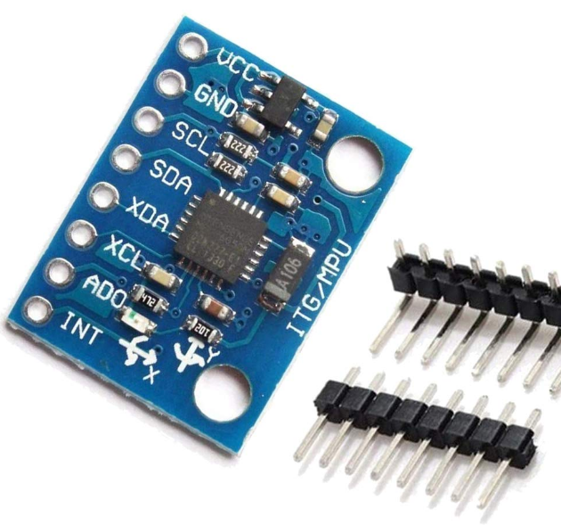
| GY 521 MPU6050 Gyro | 1 |
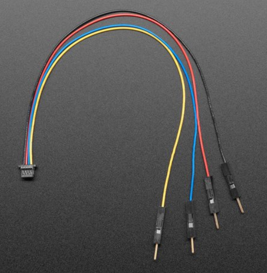
| STEMMA QT 4 Pin to Male Header | 1 |
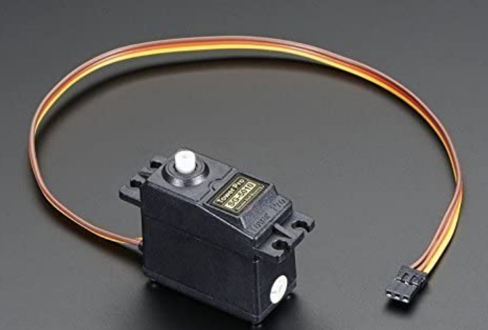
| Tower Pro SG5010 Servo | 2 |
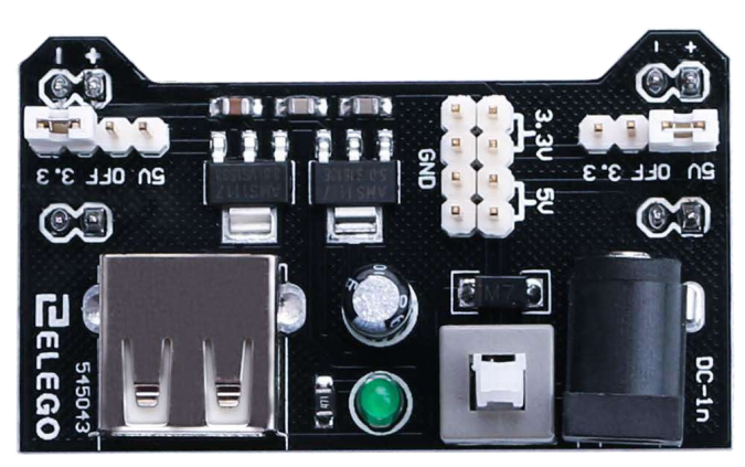
| Elego 5V Power Supply Module | 1 |
| Custom 3-D Printed Gimbal | 1 |
| Custom 3-D Printed Rocket Body | 1 (Optional) |
| Custom 3-D Printed Servo Connector | 2 |
| USB C to USB A Adapter | 1 |
| Wires | 7 |
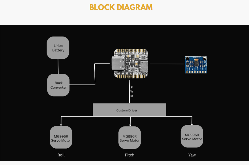
The goal of our design was to make it as simple and with as few components as possible given it needs to fit inside a model rocket. We did this by carefully selecting our components. First the Adafruit QT PY RP2040 microcontroller is extremely compact and powerful and has the ability to control all the other components. Next the GY 521 gyro is again compact and has all the capabilities we needed. The STEMMA cable was used to directly and easily connect to the sensor and controller as it has the 4 essential pins you need to operate the sensor. Next the two servos only have three pins each, one for power, ground, and the signal. Finally the power supply has enough pins on the top to supply voltage and ground to the servos and controller. It also has a USB slot that the controller can be plugged into again to cut down on wiring.
To upload the code:
Download the C SDK for the RP2040 discussed in the datasheet and install guide provided under the “Resources” tab at the top of this page. Download all the code from our GitHub repository and build the UF2 file to upload. A sample UF2 file is also provided in our repo. Once it is built drag and drop in onto the RP2040 using the file explorer tab. The code should now be uploaded and the controller can be disconnected from your computer.
To wire up the project:
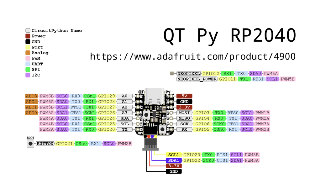
Connect the 4 pins from the STEMMA QT cable to their associated pins (Black: Ground, Red: V+, Yellow: SCL, Blue: SDA) to the matching pins on the sensor. Plug the other end into the RP2040 controller. Next plug the RP2040 into the USB adaptor and that into the power supply. On the top of the power supply connect the servos 5V (Red wire) and ground pins (Brown wire). Connect an additional ground to the ground of the RP2040. Finally connect the two servo data lines (Yellow wire) to the RP2040 GPIO pins A0 and A1. The power supply module can then be powered by a wall plug or battery pack and can be turned on with the button on top. See the pin out drawing below fr the QT PY.
3D Print Parts and Assembly
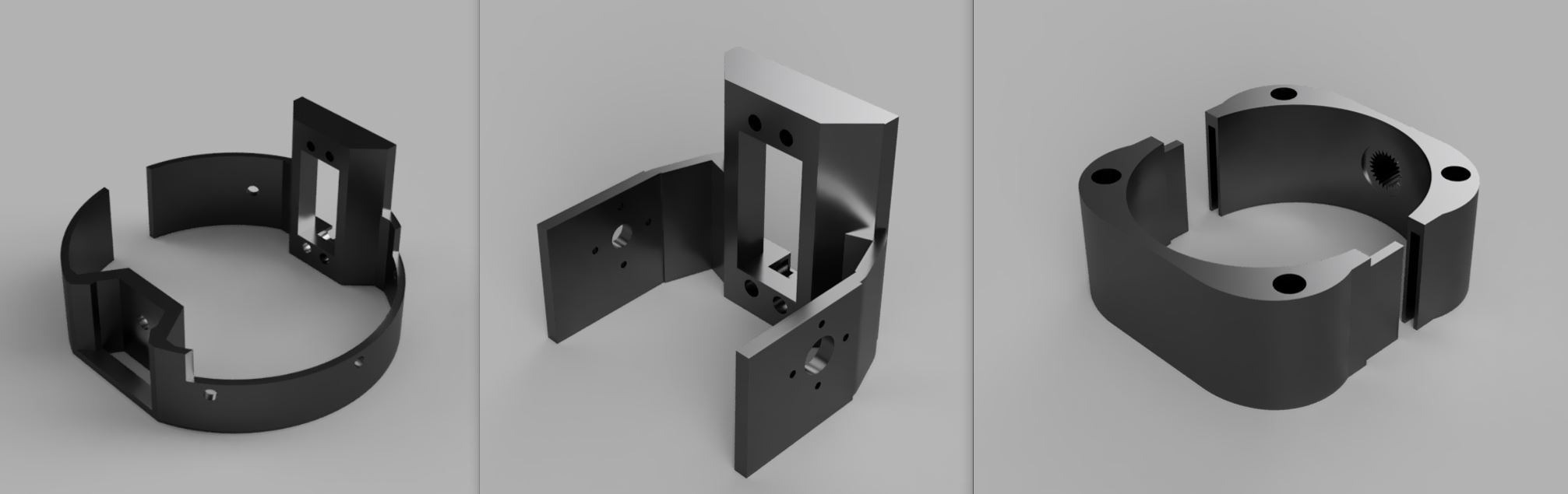
Lastly, 3-D print the three parts for the gimbal. Stick the two servo motors into the slots for them and screw them in. Connect the inner ring to the outter servo shaft and the motor holder to the inside servo shaft. After all the wires are connected and servos fitted the gimbal can be put inside a model rocket for launch.
Component Images For Reference
Custom 3-D Printed Three Component Gimbal
Adafruit QT PY RP2040
GY 521 MPU6050 Gyro
STEMMA QT 4 Pin to Male Header Cable
Tower Pro SG5010 Servo
Elego 5V Power Supply Module