Motivation:
We began this project with the initial idea of creating a gyro for a smartphone camera using the RP2040. From this initial idea is where we branched off to focus on creating it for the engine of a model rocket. Both of us have some background in aerospace engineering and rockets so we thought that this would be a more interesting alternative to a simple gyro.
Midpoint Design:
The first step was to verify our proof of concept and test the idea using Python code. Both of us have had prior experience with Python, collecting sensor data, and turning servos so to test our idea we deceided to do our initial draft using python for the bulk of the coding. With some work and preexisting python libraries we were able to pretty quickly get the MPU gyro sensor reading and turning the servos in all three axis of rotation. It did this by taking a measurment in radians/second and converted this into degrees. This degree value was then added or subtracted to the current servo reading to turn the servo the same amount the sensor moved. See below for a breif video of our midpoint design verification. Each of the three servos represents a different axis of rotation (X, Y, Z).
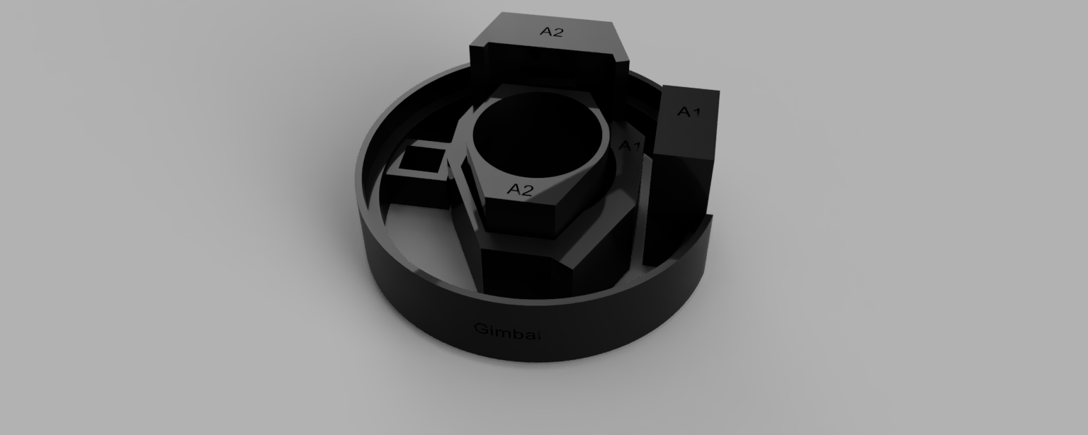
As for the 3-D printed design, we created a sample drawing in CAD and printed it to see if it would work. We found that the servos didn’t fit into it well enough to actually turn the inner componenets so we realized that the design needed to be changed and custom attachements also needed to be printed. However, we did like the material of the initial print and the size of our design soonly a few changes were necessary. Below is a rendering of our original gimbal design which after printing we realized it had to be modified.
Final Design Adjustments:
This design had a few issues such as the gyro not being perfectly zerod or the value exceeding the 180 degree limit of a servo motor. We chose to move on from the python code however without fixing these issues as they would be addresses in the final C code. From here we knew that the components and code could achieve what we were looking for, it was just a matter of transitioning our code to use C and the PIO module. To do this we initially found some sample code to get the MPU6050 sensor read over I2C and a servo to turn using the PIO module. Links to these can be seen below:
From these baseline codes we began combining them and getting both servos to turn identically to how we did with the python code previously. We deceided to only work with two axis of rotation (X & Y) as it would make the design simpler, lighter, and the Z axis does not help in stability much given the rocket is elevating anyway. The code uses the STEMMA QT cable and I2C connection to get readings from the sensor. This data feeds into the PIO module 0. The module uses state machines 0 & 1 to each control each servo. We were also able to fix our previous issues of the servos turning too much by implementing a simple if statement loop seen below.
    if (ms <= MIN_DC) {
        MPU6050_ReadData(accelerometer, gyro, &temp);
        printf("Gyro X= %d  Y= %d   Z= %d ms= %d ms1= %d\r\n",gyro0, gyro1, gyro2, ms, ms1);
        ms = MIN_DC + 10;
        ms1 += gyro2/4;
    }
    if (ms >= MAX_DC) {
        MPU6050_ReadData(accelerometer, gyro, &temp);
        printf("Gyro X= %d  Y= %d   Z= %d ms= %d ms1= %d\r\n",gyro0, gyro1, gyro2, ms, ms1);
        ms = MAX_DC - 10;
        ms1 += gyro2/4;
    }
    if (ms1 <= MIN_DC) {
        MPU6050_ReadData(accelerometer, gyro, &temp);
        printf("Gyro X= %d  Y= %d   Z= %d ms= %d ms1= %d\r\n",gyro0, gyro1, gyro2, ms, ms1);
        ms += gyro0/4;
        ms1 = MIN_DC + 10;
    }
    if (ms1 >= MAX_DC) {
        MPU6050_ReadData(accelerometer, gyro, &temp);
        printf("Gyro X= %d  Y= %d   Z= %d ms= %d ms1= %d\r\n",gyro0, gyro1, gyro2, ms, ms1);
        ms += gyro0/4;
        ms1 = MAX_DC - 10;
    }
    else {
        MPU6050_ReadData(accelerometer, gyro, &temp);
        printf("Gyro X= %d  Y= %d   Z= %d ms= %d ms1= %d\r\n",gyro0, gyro1, gyro2, ms, ms1);
        ms += gyro0/4; //100; //gyro0;
        ms1 += gyro2/4;
    }
We were also able to fix the sensor not being acurately zerod by adding or subtracting this small offset so our readings were more accurate. We left the sensor still and averaged 100 readings to get accurate offsets.
//offsets x=2, y=0 z=0
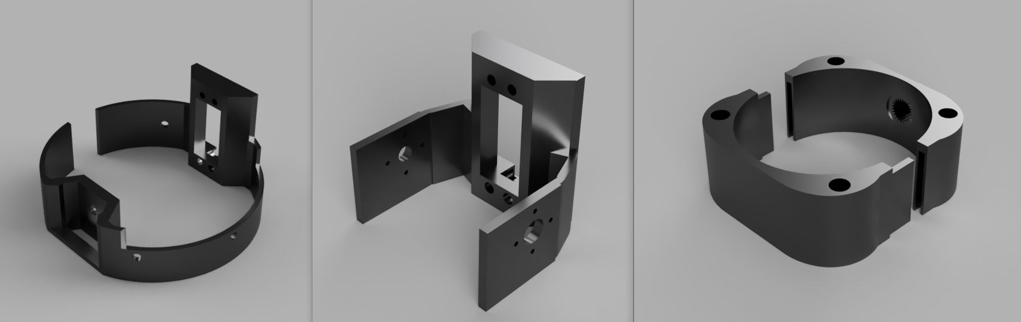
Next we also had to redesign the 3-D printed gimbal after our midpoint to give it more flexibility and properly turn. We also had to print custom servo attachments so the servos would better snap into the gimbal and turn with less resistance. To do this we split it up into three separate layers that better snap into one another. The left most layer is what holds the entire thing and has a slot for one of the servos. The middle layer snaps onto the first servo shaft so that it can be turned and holds the second servo. The right layer snaps onto the second servo shaft and is what holds the rocket engine to stabilize it.